PVEL’s Thermal Cycling (TC) test assesses a PV module’s ability to endure changes in temperature. While ambient temperatures vary daily and seasonally in most solar markets, top-performing TC results are most critical in locations where temperatures are much lower at night than during the day, typically the very places that have high solar resource.
Thermal Cycling
Why Thermal Cycling Testing Matters
Following a year of site operation, fellow Kiwa Group member PI Berlin’s team in Spain were contracted to perform a routine inspection of a 12 MW Spanish site. During this inspection the PI Berlin team discovered junction boxes with a noticeable temperature gradient via thermal imaging. Further investigations determined that 90% of the modules had junction boxes with this issue. The hottest part shown in these images was at the cable termination points inside the junction box.
The site owner spent more than 45,000€ over eight months to investigate the issue, inspecting every module on the site and conducting a root cause analysis. That analysis included PI Berlin removing the junction box pottant on a sample of affected modules and discovering a crimping issue at the cable terminations. The bypass diode placement in the junction box prevented robust crimping of the cable, leading to weakened electrical connections. This issue can lead to higher electrical resistance and therefore lower performance, and in the worst case, to hot spots, arc faults and fires.
The module manufacturer was contacted but is not considering this a valid case for warranty replacement. The site owner will continue to evaluate the module performance and electrical insulation on an annual basis, and will attempt warranty claims in the future for any modules that experience catastrophic failures.
This type of issue can be missed in the TC200 thermal cycling test of IEC 61215 but has previously been identified during the extended TC600 thermal cycling testing in PVEL’s PQP.
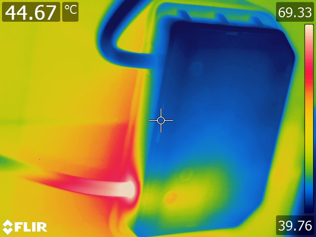
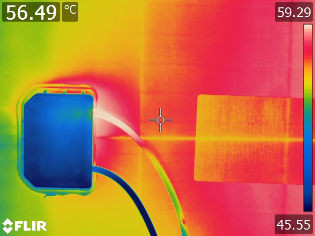
Thermal images showing hot spots at the junction box cable terminations.
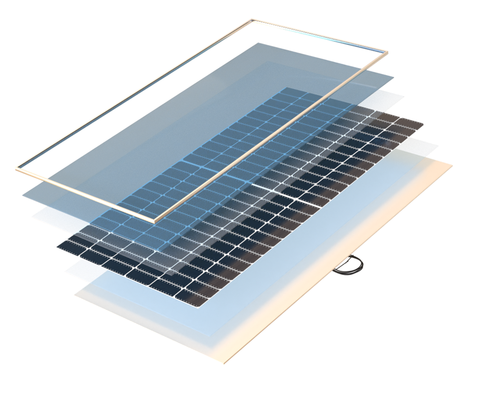
Front Encapsulant
Back Encapsulant
Cells, Cell Interconnects, Flux
Connectors, Bypass Diodes
Materials Assessed
These materials are susceptible to failure due to thermal stress and/or are critical for solder bond reliability:
- Cells
- Encapsulant
- Cell Interconnects
- Flux
- Connectors
- Bypass Diodes
- Module Size

Key Takeaways
Scroll through the key takeaways.
84% of BOMs tested degraded by < 2%.
TC results continue to be impressive with a median degradation of 1.0% following TC600 across the 2023 Scorecard test population; however, this is an increase in degradation from the 0.7% median reported in the 2022 Scorecard.
0.5% median degradation for glass//glass versus 1.8% for glass//backsheet.
Additionally, in all three cases where manufacturers tested glass//glass and glass//backsheet BOMs with identical cells, the glass//glass BOM had less than a third of the degradation of the glass//backsheet BOM.
PERC and TOPCon equally reliable. HJT soldering challenges exist.
The change to TOPCon is often coupled with a switch to 16BB cells which could present soldering difficulties, yet the TOPCon TC600 yielded good results, along with PERC. Meanwhile, the necessary low-temperature soldering for HJT modules remains a challenge for some.
Almost 12% of BOMs experienced one or more failures during TC testing.
Six manufacturers experienced at least one failure during TC testing, including some catastrophic junction box issues such as failed diodes, melted connectors, exposed wires and no output due to open solder bonds in the junction box.
Test Procedure
Modules are subjected to extreme temperature swings in an environmental chamber. They are first brought to a temperature of -40°C, after which the temperature increases to +85°C. While the temperature is increased, the modules are subjected to maximum power current providing additional field-relevant stress. The cycle repeats 600 times in total. Characterizations are conducted every 200 cycles.
IEC 61215 testing requires 200 thermal cycles, which does not represent the expected operational lifetime of a PV module in most environments. With regard to solder bond fatigue, 25 thermal cycles equates to just one year of operation in Chennai, India, but it covers 50 years in Sioux Falls, South Dakota.*
*Bosco, N.S., Silverman, T., Kurtz, S., “Climate Specific Thermomechanical Fatigue of Photovoltaic Module Solder Bonds,” Microelectronics Reliability, March 2016, DOI: 10.1016/j.microrel.2016.03.024
Power Degradation of Thermal Cycling BOMs
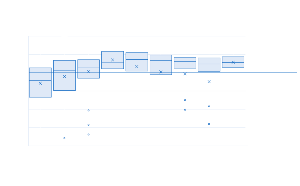
Outliers with >10% degradation are not shown. In some cases, these cause a significant reduction in the mean.

TC Test Result Spotlight
Some modules that perform well for the IEC 61215 standard’s 200 thermal cycle test duration experience catastrophic defects during the PQP extended thermal cycling. In this example, the module performed well through TC200 and TC400. However, after TC600 the module had no power output and a black EL image. PVEL investigated the failure and discovered an open circuit inside one of the module’s junction boxes. Had this been installed in the field it would have caused the entire string to have no output.
TC200
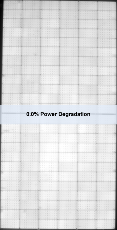
The module performs exceptionally well after TC200 with no power degradation.
TC400
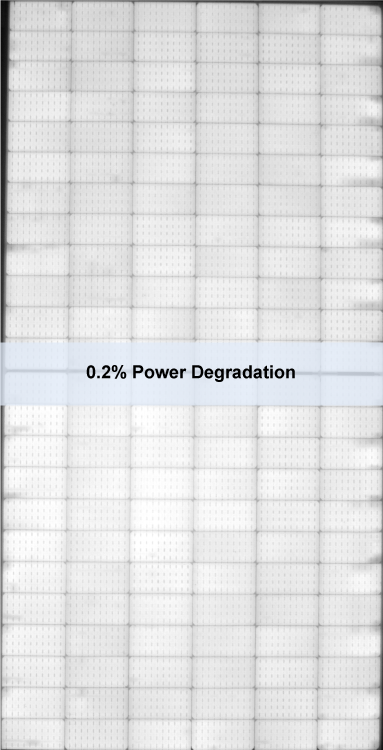
After TC400 the module still has only 0.2% power degradation.
TC600

After TC600 the module has no output due to an open circuit.